Fiber Optic Fusion Splice Welding Technique According to International Standards
A substandard fiber optic splice can cause signal attenuation 5–10 times greater than a standard splice, leading to a significant drop in data transmission speed or complete disconnection on long backbone lines. According to the International Telecommunication Union (ITU-T) standard, acceptable fiber optic splice attenuation should be below 0.1dB , while poorly executed splices by inexperienced technicians can reach 0.5–1dB—enough to cause transmission failures on cable lines tens of kilometers long.
This article details the fiber optic fusion splicing technique according to international standards — from the equipment used and the standard 5-step process to the OTDR-based quality control method, helping to ensure the long-term quality of enterprise fiber optic cables.
What is Fusion Splice and Why Is It Necessary?
Fusion splicing is a method of joining two optical fiber ends by melting and merging them into a continuous fiber using an electric arc, unlike mechanical splices which only temporarily connect the two fiber ends.
Advantages of fusion splices compared to connector/mechanical splices:
- Significantly lower attenuation (0.02–0.1dB compared to 0.3–0.5dB of mechanical splice)
- High mechanical strength, better resistance to tension and vibration.
- Suitable for backbone cable lines, underground cable lines, and outdoor overhead cable lines requiring long-term reliability.
- This procedure is mandatory when repairing fiber optic cables that are broken due to construction errors or natural disasters.
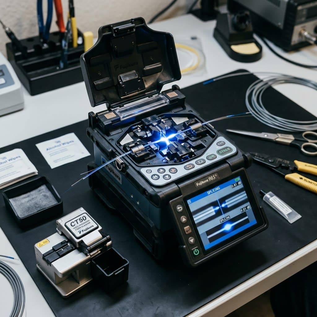
Equipment: Sumitomo and Fujikura Welding Machines
The two most popular fiber optic fusion splicers on the market are Sumitomo (Japan) and Fujikura (Japan), both of which use automatic fiber core alignment technology with high-resolution cameras.
Criteria
General purpose welding machine
High-end welding machines (Sumitomo/Fujikura)
Alignment method
Cladding alignment
High-precision core alignment
Average welding time
10–15 seconds
6–9 seconds
Average attenuation
0.03–0.1dB
0.02–0.05dB
Number of soldering cycles before needing to recharge the battery.
Less
200–300 uses per charge
Field dust and water resistance
Basic
Meets IP standards for resistance to harsh environments.
Investing in genuine welding equipment that is regularly maintained and calibrated is crucial to weld quality—skill alone cannot compensate for a deteriorated or non-standardized machine.

Standard Fiber Optic Cable Splicing Procedure: 5 Steps
Step 1: Strip the Fiber Optic Coating
- Using specialized fiber strippers, strip off the protective plastic coating, approximately 30–40 mm long, to expose the glass cladding.
- Handle gently, avoiding scratches or micro-cracks on the fiber surface—a leading cause of high attenuation and fiber breakage later on.
- Wipe away any remaining protective gel with 99% isopropyl alcohol and a lint-free wipe.
Step 2: Cut off the ends of the yarn using a specialized cutter.
- Using a high-precision fiber optic cleaver, create a 90-degree right-angle cut with an allowable error of less than 0.5 degrees.
- The length of the bare wire after cutting meets the standard of 8–16mm, depending on the type of soldering machine.
- Improper cross-sections (beveled edges, feather-like cracks) require re-cutting — this is the most common cause of faulty welds.
Step 3: Clean the Fiber Surface
- Inspect the fiber using a fiber inspection scope before feeding it into the soldering machine.
- Completely remove all dust, oil, and moisture from the surface — even a tiny dust particle can cause bubbles in the weld.
Step 4: Fusion
- Place both ends of the fiber into the fiber holder of the soldering iron, and close the protective cap.
- The machine automatically aligns the fiber core using dual cameras (XY axis), then uses an electric arc to melt and fuse the two ends of the fiber.
- The machine immediately displays the estimated loss value and a weld image for a preliminary assessment of quality — a good weld has no air bubbles, is not off-center, and does not have abnormal bulging.
Step 5: Protect the weld with heat shrink tubing.
- Thread the heat shrink protection sleeve through the fiber before welding (a step that is easily forgotten, causing you to have to start welding from the beginning).
- After welding, move the heat shrink tubing to the correct welding position and place it in the heat shrink oven integrated into the welding machine, at a temperature of approximately 200°C for 30–90 seconds.
- Heat shrink tubing protects welds from dust, moisture, and mechanical impact, and enhances the tensile strength of the joint.

Standard welding procedure checklist
- Clean the cutting blades and welding clamps before each shift.
- Inspect the fiber cross-section under a microscope before each soldering session.
- Confirm that the estimated attenuation value on the welding machine is below 0.1dB before proceeding.
- Insert the heat shrink tubing in the correct order before welding to avoid having to redo it.
- Record the loss data for each weld in the acceptance report.
Solder Loss Below 0.1dB: Acceptable Standard
According to ITU-T G.652 recommendations for single-mode fiber, a standard splice must have the following attenuation:
- Excellent: below 0.02dB
- Standard range: 0.02–0.1dB
- Resoldering required: over 0.1dB — especially with long trunk lines, this error accumulates across multiple solder joints and will seriously affect overall signal quality.
Factors affecting weld loss include: surface cleanliness, cutting angle accuracy, fiber core alignment accuracy, and the quality of the welding machine's arc (electrodes that have been used many times need to be cleaned or replaced periodically).
OTDR Testing: Full-Line Quality Confirmation
The attenuation value displayed on the splicing machine is only an estimate , not the actual measurement result. Testing with an OTDR (Optical Time Domain Reflectometer) is a mandatory step to confirm the actual quality of the entire cable line before acceptance and handover.
- An OTDR emits light pulses into the optical fiber and measures the reflected signal to precisely determine the location and attenuation level at each splice point and connector along the entire line.
- Detecting potential faults: macro-bends causing signal loss, dirty connectors, hidden fiber cracks not visible to the naked eye.
- The OTDR measurement results are output as a visual chart (trace), which is stored as official acceptance documentation for the client or investor.
- Bidirectional OTDR testing provides more accurate results than one-way testing, which is especially important for cable routes longer than 10km.

Single-Mode and Multi-Mode: Differences in Soldering
Criteria
Single-Mode Yarn
Multi-Mode Fiber
Core diameter
~9 microns
50 or 62.5 microns
Transmission distance
Tens of kilometers or more
Usually under 2km
Popular applications
Business trunk line, inter-building, telecommunications
In-building connectivity, short-range data center connectivity.
Alignment is required during welding.
Extremely accurate (small core)
Less demanding (larger core)
Cable costs
Lower
Higher
Terminal equipment (transceiver) costs
Higher
Lower
The splicing machine must be set to the correct splicing program corresponding to the type of fiber — splicing with the wrong program between single-mode and multi-mode will result in very high signal loss even with correct technique.
Workplace Safety During Fiber Optic Cable Welding
- Always wear safety glasses when cutting and handling fiber optic cables — tiny glass fiber fragments can fly into your eyes and are very difficult to detect with the naked eye.
- Do not handle the cut ends of the yarn with your bare hands; use a specialized tray to collect yarn scraps.
- Never look directly at the tip of a working fiber optic cable — infrared laser light is invisible to the naked eye but can damage the retina.
- Clean the construction area after each shift, thoroughly collecting all fiber optic debris to prevent injury to others.
Troubleshooting Common Solder Joint Problems
Even experienced technicians can encounter faulty solder joints. Correctly identifying the cause allows for quick troubleshooting and avoids wasting cable.
The phenomenon on the welding machine
Possible causes
How to fix it
Unusually high estimated attenuation (>0.3dB)
The fiber cross-section is not up to standard, and dirt remains.
Trim the ends of the yarn and clean them with isopropyl alcohol.
The weld has bubbles.
Weak electric arc, worn electrodes
Clean or replace the electrodes, and recalibrate the device.
Error "core alignment failed"
The fiber is misaligned in the clamping tray, and the cut surface is beveled.
Check the thread placement and cut it again with a new knife.
The weld joint is bulging or constricted.
The arc temperature is not suitable for the fiber type.
Check and select the correct welding program (splice program).
The wire breaks right at the weld point when tested by pulling.
The heat shrink tubing hasn't shrunk completely; it hasn't reached the desired temperature.
Re-weld and increase the time in the heat shrink oven.
Checklist for Regular Welding Machine Maintenance
- Clean the electrodes after every 500–1000 welding cycles or as recommended by the manufacturer.
- Replace the electrodes when you see signs of wear, or when air bubbles frequently appear in the weld.
- Welding machines should be calibrated every 6 months at an authorized service center.
- Store the welding machine in a moisture-proof box, away from dusty environments when not in use.
- Update the welding machine firmware as recommended by the manufacturer to optimize the calibration algorithm.
Quang Duc's Fiber Optic Cable Installation and Splicing Services
Quang Duc Electronics and Telecommunications Co., Ltd. provides professional fiber optic cable installation, splicing, and testing services:
- Our team of technicians is well-trained and uses genuine Sumitomo/Fujikura welding machines.
- We guarantee that the weld attenuation will be below 0.1dB, with complete OTDR measurement reports.
- Installation of backbone fiber optic cable, internal building fiber optic cable, and inter-branch connections.
- Emergency cable outage troubleshooting, splicing, and rapid connection restoration.
- The handover of technical acceptance documents is transparent and includes complete measurement data for each weld.
Conclude
Proper fusion splicing techniques, adhering to international standards, are not merely technical procedures but crucial to the lifespan and operational quality of an entire enterprise's fiber optic network. Investing in standard equipment, a rigorous five-step process, and comprehensive OTDR testing will help businesses avoid costly network failures in the future.
Contact Quang Duc today for advice and a quote on professional fiber optic cable installation and splicing services.
Hotline: 0903 306 126 (Mr.Vũ Trần) | Website: cameraquangduc.vn